Quantcast
Channel: Tips – SharonTools
Viewing all 15 articles
Browse latest View live

NX-OS general commands

$
0
0

Useful commands for Nexus (7000, 5000, 2000)  switches


HSRP

hsrp 102
 preempt delay minimum 60
 priority 120
 ip 172.19.102.254

Command to lock the configuration when entering configuration mode

 configure terminal lock

Show the port profiles config under the int (the inhereted config)

 show port-profile expand-interface

Show vpc usage

show vpc usage

Check witch ports are pinned to FEX Uplink port

show int e1/6 fex-int

Redistibute fex static pinning (need to update the pinning max links firts)

fex pinning redistibute 101

Disable VDC combined host names

no vdc combined-hostname

Backup license

copy licenses bootflash://license.tar
 copy bootflash://license.tar tftp://1.1.1.1/license.tar

Save commands history to disk

 archive
 log config
 logging enable
 logging size 200
 hidekeys
 notify syslog

Save log to disk

 logging buffered
 logging persistent url disk0:/syslog size 134217728 filesize 16384

Check what is synced with CFS

show cfs application

Turn on CFS over IP (over mgmt port)

cfs eth distribute
cfs ipv4 distribute

Turn on CFS for NTP

ntp distribute

Commit ntp changes when using CFS

 ntp commit

Check fabric modules status

show module xbar

Disable LAN trafic on FCoE port

 interface ethernet slot/port
 shutdown lan

Unicast RPF

 interface Ethernet2/3
 ip address 172.23.231.240/23
 ip verify unicast source reachable-via any
 show ip interface vlan 10 | i unicast

Check modules hardware capabilities

show hardware capacity forwarding

Fabric utilization

show hardware capacity fabric-utilization

Check if was an interfaces drops on a module

show hardware capacity interface

Check port quees

show policy-map interface Ethernet 1/1 input type queuing

Tern on locator led

beacon

Tern on locator led - N2K

conf t
 fex 101
 beacon

Ccancel combined-hostname at hostnames

no vdc combined-hostname

Start new evaluation for license (Only for nexus 7000)

license grace-period

Check mac address table at hardware: (UCS)

A(nxos)# show platform fwm in replmac | in %Mac%

Jumbo frames

switch(config)#system jumbomtu 9216
 switch(config)#interface ethernet x/x
 switch(config-if)#switchport
 switch(config-if)#mtu 9216
 switch(config-if)#exit
 switch(config)# policy-map type network-qos jumbo
 switch(config-pmap-nq)# class type network-qos class-default
 switch(config-pmap-c-nq)# mtu 9216
 switch(config-pmap-c-nq)# exit
 switch(config-pmap-nq)# exit
 switch(config)# system qos
 switch(config-sys-qos)# service-policy type network-qos jumbo

Upgrade nexus

 copy ftp://a@73.192.99.217/n5000-uk9-kickstart.5.1.3.N1.0.328.bin bootflash:
 copy ftp://a@73.192.99.217/n5000-uk9.5.1.3.N1.0.328.bin bootflash:
 install all kickstart bootflash:n5000-uk9-kickstart.5.1.3.N1.0.328.bin system bootflash:n5000-uk9.5.1.3.N1.0.328.bin

Clock client – NXOS
>ntp server 10.0.0.10 prefer use-vrf default
Add fex (N2K) to N5K

 fex 101
 interface port-channel101
  switchport mode fex-fabric
 vpc 101
  fex associate 101
 interface Ethernet1/1-2
  switchport mode fex-fabric
  fex associate 101
  channel-group 101

Check Po load balancing statistics

show port-channel traffic

vPC track

track 10 list boolean or
 object 11
 object 12
 track 11 interface port-channel10 line-protocol
 track 12 interface Ethernet1/1 line-protocol
 vpc domain 10
 role priority 32767
 system-priority 1
 track 10
 peer-keepalive destination 192.168.100.2 source 192.168.100.1 vrf peerkeepalive

Sync config (for Nexus 5000 vPC peers)

 cfs ipv4 distribute
 cfs eth distribute
 switch-profile sync-test
 sync-peers destination 10.10.10.252

DHCP snooping

ip dhcp snooping
 ip dhcp snooping information option
 no ip dhcp snooping verify mac-address
 no ip dhcp relay
 ip dhcp snooping vlan 1-3967,4048-4093
 interface port-channel1
 ip dhcp snooping trust
 interface Ethernet101/1/48
 ip dhcp snooping trust

Arp inspect (protect DG)

ip arp inspection vlan 1-3967
 ip arp inspection filter Protect_DG vlan 1-3967
 arp access-list Protect_DG
 10 permit ip 0.0.0.254 0.0.0.255 mac 0000.0c07.ac00 FFFF.FFFF.FF00
 20 permit ip 0.0.0.254 0.0.0.255 mac 0000.5E00.0100 FFFF.FFFF.FF00
 30 deny ip host 172.19.102.254 mac any log
 40 permit ip any mac any


The post sharon saadonNX-OS general commands appeared first on SharonTools.


Cisco Nexus VPC – best practices

$
0
0

Example topology

vpc

Cisco Nexus VPC – best practices

vpc domain 1
 peer-gateway
 peer-switch
 ip arp synchronize
 delay restore 120
 graceful consistency-check
 auto-recovery
 auto-recovery reload-delay 240

If configuring “peer-switch” vPC vlans priority on both switch must be the same !!!

Use the command spanning-tree vlan <vPC vlans> priority <priority>  on both switches


Recommendations

1. vPC domain id must be different on both layers because this
information is used as part of the LACP protocol. Using the same vPC domain id will generate continuous
flaps on vPC interconnecting the NEXUS 5000 to NEXUS 7000.

If user absolutely wants to use the same domain-id on both vPC domains, then knob system-mac(under vPC     domain configuration context) must be used to force different vPC system-mac values.
vPC system-mac and vPC local system-mac are both used in the LACP protocol as the LACP system ID
2. Spanning tree ports configuration

3. LACP mode active-active (on both sides of the port-channel) is the recommended configuration
4. If the downstream access switch is a not a Cisco Nexus device, disable the LACP graceful-convergence option.
5. vPC ports limitations:
• PIM SM (Sparse Mode) is fully interoperable with vPC. The software does not support PIM BiDIR or PIM SSM       (Source Specific Multicast) with vPC.
• The software does not support DAI (Dynamic ARP Inspection) or IPSG (IP Source Guard) in a vPC environment.
• DHCP relay and DHCP snooping are supported with vPC.
• The software does not support Cisco Fabric Services regions with vPC.
• Port security is not supported on vPC member ports.
6. Any vPC VLAN allowed on vPC member port MUST be allowed on vPC peer-link.
7. Use show vpc orphan-ports command to display all Orphan Ports on vPC peer device
8. Use same vPC ID as port-channel ID for ease ofconfiguration, monitoring, and troubleshooting
9. Configure a separate Layer 3 link for routing from the vPC peer device (backup routing path), rather than using vPC peer-link and SVI for this purpose.
10. Bridge Assurance
• Let Bridge Assurance running on vPC peer-link (default mode) and do not disable it.
• Do not use bridge assurance command for interconnect remote sites
• Do not enable Bridge Assurance on vPC member ports.
11. Create an additional Layer 2 trunk port-channel to transport non-vPC VLAN traffic(if doing so, make sure that the VLANs are not in the same MST group).
12. Use MST with vPC if you need to build a large L2 domain
13. When using vPC, it is a best practice to use default timers for HSRP, VRRP and PIM configurations.
14. vPC peer-keepalive:
• Do not configure vPC peer-keepalive link on top of vPC peer-link!!
• Use Mgmt0 interface for vPC peer-keepalive
• Do not connect mgmt0 ports in back-to-back mode across the two switches
15. vPC peer-link
• Use at least 2 different line cards to increase high availability of peer-link.
• Use dedicated 10-Gigabit Ethernet ports with M132 10G line card. Do not use shared mode ports.
• Do not insert any device between vPC peers. A peer-link is a point-to-point link
• It is mandatory that both sides of vPC peer-link are strictly identical (M1 to M1, F1 to F1, F2 to F2..)
• ports on M132XP can used for vPC peer-link only if the port is configured in dedicated mode.
• For vPC peer device with a only one M1 line card use vPC object tracking feature.
16. vPC peer-gateway
• Always enable vPC peer-gateway in the vPC domain
Use the command peer-gateway under VPC domain to allow both N7K forward traffic of each other HSRP
(even if destination MAC is of the other N7K)
• If you configure a VLAN for OSPF over the vPC, you must exclude that vlan from peer-gateway, use the     command – peer-gateway exclude-vlan .
17. vPC Peer-switch
• Configure the command peer-switch under vpc domain
• When vPC peer-swtich is activated, both vPC peer devices MUST have the same spanning tree     configuration,     same Spanning Tree Protocol priority for all vPC VLAN
18. vPC ARP Sync
• Always enable vPC ARP Sync on both vPC peer devices.
Use the command – ip arp synchronize under vpc domain
19. vPC delay restore
• Always enable vPC delay restore (on both vPC peer devices) and the tune the timer accordingly based on network profile.
Use the command – delay restore under vpc domain
20. vPC graceful type-1 check
• Always enable vPC graceful type-1 check on both vPC peer devices.
Use the command – graceful consistency-check under vpc domain (enabled by default)
21. vPC auto-recovery
• Always enable vPC auto-recovery on both vPC peer devices
Use the command – auto-recovery under vpc domain
22. vPC auto-recovery reload-delay
• Always enable vPC auto-recovery reload-delay on both vPC peer devices.
Use the command – auto-recovery reload-delay under vpc domain
23. When connecting a Cisco Nexus device to a Cisco Catalyst device, be cautious with the VLAN used for that purpose in order to avoid any reserved VLANs from the NX-OS range or IOS range.
(IOS reserve vlans 1006-1018, NX-OS reserve vlans 3968-4094)
24. Attaching a L3 device (router or firewall configured in routed mode for instance) to vPC domain using a vPC is not
a supported design because of vPC loop avoidance rule.
(Need to connect with ECMP L3 links)
25. Enable Layer 3 connectivity between vPC peer device by configuring a VLAN network interface for the
same VLAN from both devices or by using a dedicated L3 link between the 2 peer devices (for L3 backup
routing path purposes).


Good to know

General
A Layer 2 port-channel only is supported with vPC (no Layer 3)

vPC Data-Plane Loop Avoidance
vPC performs loop avoidance at data-plane layer instead of control plane layer for Spanning Tree Protocol.
All logics are implemented directly in hardware on vPC peer-link ports, avoiding any dependancy to CPU utilization.
vPC peer devices always forward traffic locally when possible,
vPC loop avoidance rule states that traffic coming from vPC member port, then crossing vPC peer-link is NOT
allowed to egress any vPC member port; however it can egress any other type of port (L3 port, orphan port, …).

vPC Role
(primary / secondary)
vPC role defines which of the two vPC peer devices processes Bridge Protocol Data Units (BPDUs) and responds to Address Resolution Protocol (ARP).
When vPC peer-link is down, The secondary peer device shut down vPC member ports.

CFS
Cisco Fabric Services (CFS) protocol performs the following functions:
● Configuration validation and comparison (consistency check)
● Synchronization of MAC addresses for vPC member ports
● vPC member port status advertisement
● Spanning Tree Protocol management
● Synchronization of HSRP and IGMP snooping
Cisco Fabric Services is enabled by default when vPC feature is turned on.

vPC Peer-Link
The vPC peer-link is a standard 802.1Q trunk that can perform the following actions:
● Carry vPC and non-vPC VLANs.
● Carry Cisco Fabric Services messages that are tagged with CoS=4 for reliable communication.
● Carry flooded traffic from the other vPC peer device.
● Carry STP BPDUs, HSRP hello messages, and IGMP updates.
vPC peer-link is supported on all shipping 10G line card. It is not supported on any 1G line card nor on any FEX
ports (including the 2232 model which has 10G front panel ports).

vPC peer-gateway
allow both N7K forward traffic of each other
a knob is available to exclude specific VLANs from the peer-gateway.
These VLANs are typically used for backup routing paths. The command is:
N7k(config-vpc-domain)# peer-gateway exclude-vlan

vPC Peer-Switch
The vPC Peer-Switch feature (Figure 42) allows a pair of vPC peer devices to appear as a single Spanning Tree
Protocol root in the Layer 2 topology (they have the same bridge ID). vPC peer-switch must be configured on both
vPC peer devices to become operational. The command is the following:
N7K(config-vpc-domain)# peer-switch

HSRP/VRRP active/active with vPC
HSRP and VRRP operate in active-active mode from data plane standpoint (by default), as opposed to classical active/standby
implementation with STP based network.

HSRP/VRRP – Active/Active/Active (core and DR sites)
DCI_1-32

PACL configuration to stop HSRPv1 hello messages:

ip access-list HSRPv1_Filtering
 10 deny udp any 224.0.0.2/32 eq 1985
 20 permit ip any any

PACL configuration to stop HSRPv2 hello messages:

ip access-list HSRPv2_Filtering
 10 deny udp any 224.0.0.102/32 eq 1985
 20 permit ip any any

PACL configuration to stop VRRP hello messages:

ip access-list VRRP_Filtering
10 deny udp any 224.0.0.18/32 eq 1985
20 permit ip any any

To apply the PACL to DCI vPC link, apply the PACL on each member ports (example with HSRPv1):

Interface Po10
 ip port access-group HSRPv1_Filtering


The post sharon saadonCisco Nexus VPC – best practices appeared first on SharonTools.

Linux – telnet source ip not shown

$
0
0

under linux you can find the client source ip with the command-

sharon@lab:~$ who am i
 sharon pts/0 2013-02-23 23:31 (10.0.0.10)

or better with-

sharon@lab:~$ who am i | awk '{print $5}'|sed 's/.\(.*\)./\1/'
10.0.0.10

For some reason in new debian versions it will not show you the ip address if connected via telnet

sharon@lab:~$ who am i
sharonsa pts/1 2013-02-23 23:44

‘last -i’ showing 0.0.0.0 instade of my client ip-

sharons@lab:~$ last -i | grep "still logged in"
sharons pts/1 0.0.0.0 Sat Feb 23 23:44 still logged in
sharons pts/0 10.0.0.10 Sat Feb 23 23:31 still logged in


I solved it by adding a script to ~/.bashrc

the script finds the last telnet connection source IP address,
Then you can add the IP to a log file or do whatever you need..

sharon@lab:~$ echo $(echo $(netstat -nae | grep $(netstat -nae | grep 23 | awk '{print $8}' | sort -n | tail -n1) | awk '{print $5}') | awk -F':' '{print $1}' )
10.0.0.12

To use in a script – replace ‘echo’ with the variable name

sharon@lab:~$ telnet_ip= $(echo $(netstat -nae | grep $(netstat -nae | grep 23 | awk '{print $8}' | sort -n | tail -n1) | awk '{print $5}') | awk -F':' '{print $1}' )


You can practice in linux (Debian) at the the online lab-

http://www.sharontools.com/online-lab/


The post sharon saadonLinux – telnet source ip not shown appeared first on SharonTools.

Avaya (Nortel) 8600 CPU utilization

$
0
0

It is recommended that you look at Nortel 8600 CPU utilization

While making changes in the network / Configuration

The problem is that the Graph scale allways changing and it hard to understand what is the Utilization

You can fix it in this way:

1. Click at JDM (Java Device Manager) - Graph -> Chassis
8600-cpu


2. Click the CPU field
3. Click the graph button
8600-cpu

4. Rigth click the graph
8600-cpu

5. Click Axes -> Scale
6. Enter:
Axis Min: 1
Axis Max: 100
Origin: 1
7. Click Enter
Now you can understand the graph :)
8600-cpu


The post sharon saadonAvaya (Nortel) 8600 CPU utilization appeared first on SharonTools.

Nortel (Avaya) Tips

$
0
0


Tips

Stop the “more” question at long output (like “terminal length 0″ at cisco)

conf cli more false


reset to factory default

config bootconfig flags factorydefaults true


To enter to the second cpu at the chace

peer telnet


images

p80a4111 -  ios

p80b4111 -  monitor

p80c4111 -  SSH   

p80j4111 -  R MODEL

p80p4111 -  POS

p80t4111 -  ATM

p80s4111 -  SSL


The post sharon saadonNortel (Avaya) Tips appeared first on SharonTools.

Show current hierarchical configuration for nexus switches

$
0
0


An alias I made for Cisco nexus switches  to show the current hierarchical configuration

(Works like cur in Alteon)

Exampe

SW1-1(config)# int e3/9
SW1-1(config-if)# cur
interface Ethernet3/9
  switchport
  switchport mode trunk
  switchport trunk native vlan 70
  switchport trunk allowed vlan 70,100
  no shutdown
SW1-1(config-if)# vdc SW1-4
SW1-1(config-vdc)# cur
vdc SW1-4 id 4
  limit-resource module-type m1 f1 m1xl 
  allocate interface Ethernet1/25-32
  allocate interface Ethernet2/25-32
  allocate interface Ethernet3/31-48
  boot-order 1
  limit-resource vlan minimum 16 maximum 4094
  limit-resource monitor-session minimum 0 maximum 2
  limit-resource monitor-session-erspan-dst minimum 0 maximum 23
  limit-resource vrf minimum 2 maximum 4096
  limit-resource port-channel minimum 0 maximum 768
  limit-resource u4route-mem minimum 8 maximum 8
  limit-resource u6route-mem minimum 4 maximum 4
  limit-resource m4route-mem minimum 8 maximum 8
  limit-resource m6route-mem minimum 5 maximum 5
SW1-1(config-if)# 


The alias

cli alias name cur where detail | sed -n 2p | sed "s/^ *//" | sed "s/^/show run | sec '^/" | sed "s/$/$'/" | vsh


The post sharon saadonShow current hierarchical configuration for nexus switches appeared first on SharonTools.

UCS Boot From San troubleshooting

$
0
0

How to check why a UCS blade server can’t boot from san

UCS-LAB-A# connect adapter 1/4/1
adapter 1/4/1 # 
adapter 1/4/1 # connect
adapter 1/4/1 (top):1# 
adapter 1/4/1 (top):1# attach-fls
adapter 1/4/1 (fls):1# 
adapter 1/4/1 (fls):1# vnic
---- ---- ---- ------- -------
vnic ecpu type state   lif
---- ---- ---- ------- -------
7    1    fc   active  4
8    2    fc   active  5
adapter 1/4/1 (fls):2# 
adapter 1/4/1 (fls):2# lunlist 7
vnic : 7 lifid: 4
  - FLOGI State : flogi est (fc_id 0x910001)
  - PLOGI Sessions
     - WWNN 50:0a:09:81:88:dd:97:bf WWPN 50:0a:09:81:88:dd:97:bf fc_id 0x910003
       - LUN's configured (SCSI Type, Version, Vendor, Serial No.)
           LUN ID : 0x000a000000000000 (0x0, 0x4, NETAPP  , P4DsRoviYRlA)
       - REPORT LUNs Query Response
           LUN ID : 0x0004000000000000
           LUN ID : 0x000a000000000000
  - Nameserver Query Response
     - WWPN : 50:0a:09:81:88:dd:97:bf


You can see that:

  • The vnic command shows Server’s vHBAs (7 & 8, one for each fabric)
  • the configuration at the UCS is to boot from WWPN 50:0a:09:81:88:dd:97:bf, LUN 10 (0×10) (Marked yellow)
  • The server has access to WWPN 50:0a:09:81:88:dd:97:bf, Luns 4 & 10 (Marked brown)
      so Zonning (At the  MDS) and Lun masking (At NetApp) are OK, and the server will Boot


The post sharon saadonUCS Boot From San troubleshooting appeared first on SharonTools.

How to connect iSCSI Servers to a FC storage

$
0
0

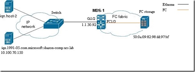
How to configure MDS switch to connect iSCSI Servers (Initaiators) to a FC storage(Target)

Topology

VirtualTargetB

Configuration

feature iscsi
iscsi enable module 1

iscsi authentication none

!! Set PWWN to client IP address
iscsi initiator ip-address 10.100.70.150
  static pWWN 20:01:00:0d:ec:16:74:42

!! Set virtual target for client
iscsi virtual-target name disc.for.iscsi.target-1
  pWWN 50:0a:09:82:98:dd:97:bf fc-lun 0x001e iscsi-lun 0x001e
  advertise interface GigabitEthernet1/2
  initiator ip address 10.100.70.150 permit

  
interface GigabitEthernet1/2
  ip address 1.1.30.92 255.255.255.0
  no shutdown
interface iscsi1/2
  no shutdown
  
vsan database
  vsan 30 name "For_iSCSI"
  vsan 30 interface iscsi1/2
  vsan 30 interface fc1/3  

!! Configure zones, in this case- allow all

zone default-zone permit vsan 30


Test

MDS-1(config)# show flogi database 
--------------------------------------------------------------------------------
INTERFACE        VSAN    FCID           PORT NAME               NODE NAME       
--------------------------------------------------------------------------------
fc1/3            30    0xef0000  50:0a:09:82:98:dd:97:bf 50:0a:09:80:88:dd:97:bf
                           [Disk2]
iscsi1/2         30    0xef0001  20:01:00:0d:ec:16:74:42 20:02:00:0d:ec:16:74:42

Total number of flogi = 2.

MDS-1(config)# 
MDS-1(config)# show iscsi session 
Initiator 10.100.70.150
  Initiator name iqn.1991-05.com.microsoft:sharon-comp.ucs.lab 
  Session #1
    Target disc.for.iscsi.target-1
    VSAN 30, ISID 400001370000, Status active, no reservation

The post sharon saadonHow to connect iSCSI Servers to a FC storage appeared first on SharonTools.


FC – How to save Device-aliases as name

$
0
0

If you wants that device aliases will be saved in zone configuration as name instead of WWPN

You can use  enhanced device-alias-

device-alias mode enhanced


Show commands

MDS-2(config)# show zoneset active 
zoneset name ML2_DC_A vsan 188
  zone name ML2_DC_WWPN_A1 vsan 188
  * fcid 0x050000 [device-alias Disk1]
    device-alias DC_WWPN_A1
  
  zone name ML2_DC_WWPN_A2 vsan 188
  * fcid 0x050000 [device-alias Disk1]
    device-alias DC_WWPN_A2
  
  zone name ML2_DC_WWPN_A3 vsan 188
  * fcid 0x050000 [device-alias Disk1]
    device-alias DC_WWPN_A3
  
  zone name ML2_DC_WWPN_A4 vsan 188
  * fcid 0x050000 [device-alias Disk1]
    device-alias DC_WWPN_A4

zoneset name ML2_DC_B vsan 299
  zone name ML2_DC_WWPN_B1 vsan 299
  * fcid 0x160000 [device-alias Disk2]
    device-alias DC_WWPN_B1
  
  zone name ML2_DC_WWPN_B2 vsan 299
  * fcid 0x160000 [device-alias Disk2]
    device-alias DC_WWPN_B2
  
  zone name ML2_DC_WWPN_B3 vsan 299
  * fcid 0x160000 [device-alias Disk2]
    device-alias DC_WWPN_B3
  
  zone name ML2_DC_WWPN_B4 vsan 299
  * fcid 0x160000 [device-alias Disk2]
    device-alias DC_WWPN_B4

MDS-2(config)#
MDS-2(config)# sh run | i alias
device-alias mode enhanced
device-alias database
  device-alias name Disk1 pwwn 50:0a:09:81:88:dd:97:bf
  device-alias name Disk2 pwwn 50:0a:09:82:98:dd:97:bf
  device-alias name DC_WWPN_A1 pwwn 20:00:00:25:b5:a0:00:00
  device-alias name DC_WWPN_A2 pwwn 20:00:00:25:b5:a0:00:01
  device-alias name DC_WWPN_A3 pwwn 20:00:00:25:b5:a0:00:02
  device-alias name DC_WWPN_A4 pwwn 20:00:00:25:b5:a0:00:03
  device-alias name DC_WWPN_B1 pwwn 20:00:00:25:b5:b0:00:00
  device-alias name DC_WWPN_B2 pwwn 20:00:00:25:b5:b0:00:01
  device-alias name DC_WWPN_B3 pwwn 20:00:00:25:b5:b0:00:02
  device-alias name DC_WWPN_B4 pwwn 20:00:00:25:b5:b0:00:03
device-alias commit

MDS-2(config)# sh run zone 

!Command: show running-config zone
!Time: Sun Sep 14 03:00:06 1980

version 4.2(9)
zone mode enhanced vsan 188
zone mode enhanced vsan 299
!Active Zone Database Section for vsan 188
zone name ML2_DC_WWPN_A1 vsan 188
    member device-alias Disk1
    member device-alias DC_WWPN_A1

zone name ML2_DC_WWPN_A2 vsan 188
    member device-alias Disk1
    member device-alias DC_WWPN_A2

zone name ML2_DC_WWPN_A3 vsan 188
    member device-alias Disk1
    member device-alias DC_WWPN_A3

zone name ML2_DC_WWPN_A4 vsan 188
    member device-alias Disk1
    member device-alias DC_WWPN_A4

zoneset name ML2_DC_A vsan 188
    member ML2_DC_WWPN_A1
    member ML2_DC_WWPN_A2
    member ML2_DC_WWPN_A3
    member ML2_DC_WWPN_A4

zoneset activate name ML2_DC_A vsan 188
do clear zone database vsan 188
!Full Zone Database Section for vsan 188
zone name ML2_DC_WWPN_A1 vsan 188
    member device-alias Disk1
    member device-alias DC_WWPN_A1

zone name ML2_DC_WWPN_A2 vsan 188
    member device-alias Disk1
    member device-alias DC_WWPN_A2

zone name ML2_DC_WWPN_A3 vsan 188
    member device-alias Disk1
    member device-alias DC_WWPN_A3

zone name ML2_DC_WWPN_A4 vsan 188
    member device-alias Disk1
    member device-alias DC_WWPN_A4

zoneset name ML2_DC_A vsan 188
    member ML2_DC_WWPN_A1
    member ML2_DC_WWPN_A2
    member ML2_DC_WWPN_A3
    member ML2_DC_WWPN_A4

zone commit vsan 188
!Active Zone Database Section for vsan 299
zone name ML2_DC_WWPN_B1 vsan 299
    member device-alias Disk2
    member device-alias DC_WWPN_B1

zone name ML2_DC_WWPN_B2 vsan 299
    member device-alias Disk2
    member device-alias DC_WWPN_B2

zone name ML2_DC_WWPN_B3 vsan 299
    member device-alias Disk2
    member device-alias DC_WWPN_B3

zone name ML2_DC_WWPN_B4 vsan 299
    member device-alias Disk2
    member device-alias DC_WWPN_B4

zoneset name ML2_DC_B vsan 299
    member ML2_DC_WWPN_B1
    member ML2_DC_WWPN_B2
    member ML2_DC_WWPN_B3
    member ML2_DC_WWPN_B4

zoneset activate name ML2_DC_B vsan 299
do clear zone database vsan 299
!Full Zone Database Section for vsan 299
zone name ML2_DC_WWPN_B1 vsan 299
    member device-alias Disk2
    member device-alias DC_WWPN_B1

zone name ML2_DC_WWPN_B2 vsan 299
    member device-alias Disk2
    member device-alias DC_WWPN_B2

zone name ML2_DC_WWPN_B3 vsan 299
    member device-alias Disk2
    member device-alias DC_WWPN_B3

zone name ML2_DC_WWPN_B4 vsan 299
    member device-alias Disk2
    member device-alias DC_WWPN_B4

zoneset name ML2_DC_B vsan 299
    member ML2_DC_WWPN_B1
    member ML2_DC_WWPN_B2
    member ML2_DC_WWPN_B3
    member ML2_DC_WWPN_B4

zone commit vsan 299


The post sharon saadonFC – How to save Device-aliases as name appeared first on SharonTools.

Important tips for installing CiscoWorks 3.2

$
0
0

First get your copy of ciscoworks 3.2 from-

www.cisco.com

Before installing

  • Set computer name
  • Set IP addresses and make sure Interface is UP !
  • Check that you can ping your computer name
  • Make sure that your computer name resolved to your Interface IP (Not 127.0.0.1),

If you change it later you will have a lot of problems..

  • Data restore allowed only from the same CiscoWorks version (It’s Not possible to restore a backup from LMS 3.2 to LMS 3.2.1)

Test

(From the Server)

C:\>echo %computername%
CISCOWORKSPC

C:\>ipconfig
Windows IP Configuration

Ethernet adapter Local Area Connection:

   Connection-specific DNS Suffix  . :
   IPv4 Address. . . . . . . . . . . : 10.0.0.100
   Subnet Mask . . . . . . . . . . . : 255.255.255.0
   Default Gateway . . . . . . . . . : 10.0.0.254

C:\>ping CISCOWORKSPC

Pinging CiscoWorksPC [10.0.0.100] with 32 bytes of data:
Reply from 10.0.0.100: bytes=32 time<1ms TTL=128

Ping statistics for 10.0.0.100:
    Packets: Sent = 4, Received = 4, Lost = 0 (0% loss),
Approximate round trip times in milli-seconds:
    Minimum = 0ms, Maximum = 0ms, Average = 0ms


Compute-name must resolve to Interface IP address,

If not Edit ‘hosts’ file (usually located at – C:\Windows\System32\drivers )

and make sure you have this two lines:

>127.0.0.1 localhost
10.0.0.100 CiscoWorksPC

(At second line – Interface IP address, Computer name)


Supported OS

◦ Windows 2003 Standard and Enterprise Editions with Service Pack 2 (32 and 64 Bit)

◦ Windows 2003 Standard R2 and Enterprise R2 Editions with Service Pack 2 (32 and 64 Bit)

◦ Windows XP with Service Pack 2, Service Pack 3

◦ Windows Vista Business Edition (English and Japanese only) and SP1

◦ Windows 2008 Standard and Enterprise (32 and 64 bit)


installation

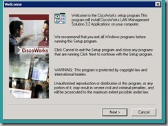
Run installation file - lms-3-2-Win-eval.exe

inst1

Click Next


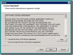
inst2

Click ‘I accept’, Next


inst3

Choose ‘Custom’, Next


inst4

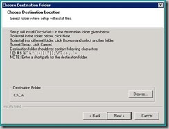
Click Browse and change installation folder to a folder that will be easy to access from DOS

(a lot of the changes to the CiscoWorks server done from DOS)


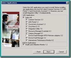
inst5

Check all, Click Next


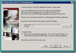
inst6

If you do not have license - Choose Later, Next


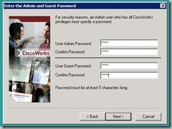
inst7

I uses a same easy password for all users, click Next


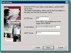
inst8

Enter SMTP information, if you do not have it, just enter some IP and click Next


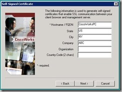
inst9

Nothing to do here, Click Next


inst10

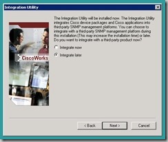
Choose ‘integrate later’, Next


inst11

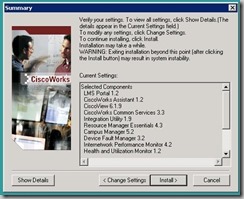
Click Next


inst12

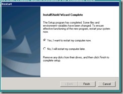
Few hours later.. Click finish

Computer will be restarted


Run1

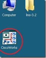
Run CiscoWorks


Run2

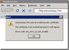
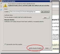
Click OK for the Certificate Error

(FireFox is my default browser)

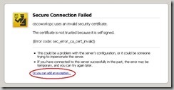
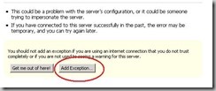
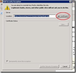
Now we will Allow this Server’s certificate

Run3

Run4

Run5

Run6

Run7

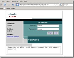
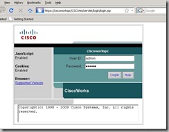
Login page, Username – admin, Password- as you configured at the installation

Run7a

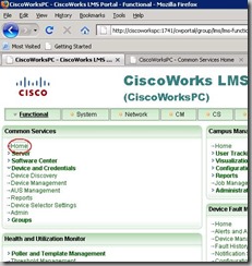
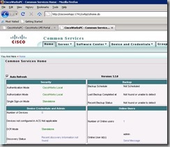
Click Home – we need to check that there are no Internal server communication errors

Run7b

All looks OK Smile


Troubleshooting

1. Empty page after entering Username and password

(Because of redirect Loop)

Run7

Fix

Fix host file (as show in this post), restart the server

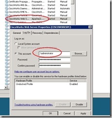
If it’s not helps, change ‘Cisco web server’ service -  logon user from local to Administrator

Fix1

Restart the service

2. error when trying to access Devices and Credentials-

Error in communicating with DCR Server.
DCR Server may be down. Please start the DCR Server and then refresh the page.

Error2

Fix

Check that Service is running

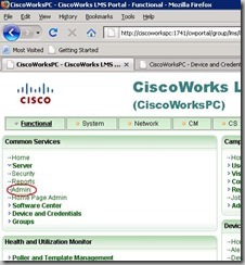
Run8

Click Admin


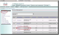
Fix2

Click Processes and check DCRServer status, make sure it’s running,

If it’s running but the server can’t communicate make sure that you can ping Computer’s name

This Service allow communication only with Server Network Interface’s IP addresses (Not 127.0.0.1)

The communication with this service is done using computer name.


Test

(From the Server)

C:\>echo %computername%
CISCOWORKSPC

C:\>ipconfig
Windows IP Configuration

Ethernet adapter Local Area Connection:

   Connection-specific DNS Suffix  . :
   IPv4 Address. . . . . . . . . . . : 10.0.0.100
   Subnet Mask . . . . . . . . . . . : 255.255.255.0
   Default Gateway . . . . . . . . . : 10.0.0.254

C:\>ping CISCOWORKSPC

Pinging CiscoWorksPC [10.0.0.100] with 32 bytes of data:
Reply from 10.0.0.100: bytes=32 time<1ms TTL=128

Ping statistics for 10.0.0.100:
    Packets: Sent = 4, Received = 4, Lost = 0 (0% loss),
Approximate round trip times in milli-seconds:
    Minimum = 0ms, Maximum = 0ms, Average = 0ms


Compute-name must resolve to Interface IP address,

If not Edit ‘hosts’ file (usually located at – C:\Windows\System32\drivers )

and make sure you have this two lines:

>127.0.0.1 localhost
10.0.0.100 CiscoWorksPC

(At second line – Interface IP address, Computer name)


Restore backup

Restore a backup from the old server

>1. stop services
net stop crmdmgtd

2. restore
perl C:\CW\bin\restorebackup.pl -d C:\temp\backup -gen 0

3. check log
notepad C:\CW\log\restorebackup.log

4. start services
net start crmdmgtd


Reset admin Password

When you restore backup, users also resotres

In case that you do not know the password for admin user you can reset the password

>1 Stop the CiscoWorks Server Daemon Manager by entering:
net stop crmdmgtd

2 Go to NMSROOT\bin directory and enter:
c:\CW\bin\resetpasswd admin

A message appears:
Enter new password for username:

3 Enter the new password for username

4 Start the CiscoWorks Server Daemon Manager by entering:
net start crmdmgtd


The post sharon saadonImportant tips for installing CiscoWorks 3.2 appeared first on SharonTools.

Alcatel omniswitch commands

$
0
0

These commands are for R6 & R7

——- general ———
ip interface vlan223 address 172.22.23.2 mask 255.255.255.0 admin-state enable vlan 223
ip interface vlan333 address 172.23.33.3 mask 255.255.255.0 admin enable vlan 333
vlan 13 members port 1/3 untagged
vlan 2 members port 1/4 tagged
vlan 13 port default 1/3
vlan 2 802.1q 1/4
modify running-directory working
ip route-map local-to-rip sequence-number 10 action permit
ip route-map local-to-rip sequence-number 10 match ip-address 0.0.0.0/0 redist-control all-subnets
ip redist local into rip route-map local-to-rip


— .1x —
vlan port mobile 1/1
vlan port 1/1 802.1x enable
aaa radius-server rad1 host 192.168.100.102 timeout 25 key alcatel-lucent
aaa authentication 802.1x rad1

ip helper … (no need to specify vlan ID)

— UNP —

no aaa user-network-profile name Berlin
no policy list policy-berlin
no policy rule policy-berlin
no policy action policy-berlin
no policy condition policy-berlin
policy condition policy-berlin source ip 192.168.4.0 mask 255.255.255.0 destination ip 192.168.2.0 mask 255.255.255.0
policy action policy-berlin disposition deny
policy rule policy-berlin condition policy-berlin action policy-berlin
policy list policy-berlin type unp enable rules policy-berlin

qos apply
aaa user-network-profile name Berlin vlan 4 policy-list-name policy-berlin
— traffic ACL —
! it’s automaticly applied to all ports !!
policy condition v10 source ip 10.0.10.0 mask 255.255.255.0 destination ip 10.0.30.0 mask 255.255.255.0
policy action v10 disposition drop
policy rule v10 condition v10 action v10

— MSTP —
spantree mode flat
spantree cist protocol mstp
spantree mst region name France
spantree msti 1
spantree msti 1 vlan 31
spantree msti 2
spantree msti 2 vlan 32
bridge mode flat
bridge cist protocol mstp
bridge mst region name France
bridge msti 1
bridge msti 1 vlan 31
bridge msti 2
bridge msti 2 vlan 32

— disable stp for a vlan —
spantree vlan 12 admin-state disable

vlan 12 stp disable

—- LACP —-
interfaces 1/3 admin-state enable
linkagg lacp port 1/3 actor admin-key 3
linkagg lacp agg 3 size 2 actor admin-key 3
vlan 31-32 members linkagg 3 tagged
interfaces 1/4 admin up
lacp linkagg 2 size 8 actor admin key 2
lacp agg 1/4 actor admin key 2
vlan 32 802.1q 2
— OSPF —-
ip load ospf
ip ospf area 0.0.0.13
ip router router-id 1.1.1.1
ip ospf admin-state enable
ip ospf interface vlan13
ip ospf interface vlan13 area 0.0.0.13
ip ospf interface vlan13 admin-state enable
ip ospf interface vlan13 auth-type md5
ip ospf interface vlan13 md5 1
ip ospf interface vlan13 md5 1 key 123456
ip ospf interface vlan13 admin-state enable
ip load ospf
ip ospf area 0.0.0.13
ip router router-id 3.3.3.3
ip ospf status enable
ip ospf interface vlan13
ip ospf interface vlan13 area 0.0.0.13
ip ospf interface vlan13 status enable
ip ospf interface vlan13 auth-type md5
ip ospf interface vlan13 md5 1
ip ospf interface vlan13 md5 1 key 123456
ip ospf interface vlan13 status enable
— ospf virtual link —-
ip ospf virtual-link 0.0.0.13 1.1.1.1
ip ospf virtual-link 0.0.0.13 1.1.1.1 auth-type simple
ip ospf virtual-link 0.0.0.13 1.1.1.1 auth-key 123456
— ospf summery —
ip ospf area 0.0.0.10 range summary 172.21.0.0 255.255.0.0

— ospf aggrigate —
ip access-list local_agg
ip access-list local_agg address 172.31.0.0/16
ip access-list local_agg address 172.31.0.0/16 redist-control agregate
ip route-map local-to-ospf-agg sequence-number 10 action permit
ip route-map local-to-ospf-agg sequence-number 10 match ip-addresss local_agg
ip redist local into ospf route-map local-to-ospf-agg admin-state enable

— IGMP —
ip multicast admin-state enable

ip multicast status enable
for PIM devices:
ip multicast querying enable

for L2 devices:
ip multicast querier-forwarding enable

— PIM —
ip load pim
ip pim sparse admin-state enable

ip pim sparse status enable
ip pim interface Loopback0
ip pim candidate-rp 1.1.1.1 225.2.2.0/24
ip pim cbsr 1.1.1.1 (this is must to advertise the rp address to all other routers)

— VRRP —-
vrrp 10 10
vrrp 10 10 priority 150 preempt interval 1
vrrp 10 10 address 172.25.10.254

— SLB —
ip slb admin enable
ip slb cluster “vip1” vip 172.25.30.100
ip slb server ip 172.25.30.10 cluster “vip1”
ip slb server ip 172.25.30.20 cluster “vip1”

—- snmp —-
user public password alcatel-lucent read-write all
aaa authentication snmp “local”
snmp security no-security
snmp community-map mode enable
snmp community-map “public” user “pablic” enable
snmp station 192.168.100.102 public v2 enable


The post sharon saadonAlcatel omniswitch commands appeared first on SharonTools.

Juniper EX switches configuration examples

$
0
0

Very useful commands for juniper EX  switches

How to configure Interfaces, OSPF, Voip, LLDP, QOS, Access lists, Routes

and more

General commands

show mac-address table

show ethernet-switching table brief

show switches that directly conected

show lldp neighbors

config vlan

set vlans  Floor_Users vlan-id 90
set vlans Floor_Users l3-interface vlan.90
set interfaces vlan unit 90 family inet address 10.10.10.254/24

assign vlan to port

set interfaces  unit 0 family ethernet-switching vlan members

upgrade (mybe needed – set system services ftp, when upgrading 8200 need to upgrage both Route Engines)

request system software add ftp://a:123456@10.10.10.81/jinstall-ex-3200-9.6R1.13-domestic-signed.tgz

enable SSH

set system services ssh

show ip addresses

show interfaces terse

show all ports info

show interfaces extensive

load factory-default

load factory-default

show rollback 10

file show /var/db/config/juniper.conf.10.gz

show int statistics at real time

run monitor interface ge-0/0/0

like tcpdump

run monitor traffic interface ge-0/0/0

to add config from notepad

load update terminal

static route

 set routing-options static route 192.168.16/24 next-hop 1.1.1.1

start terminal monitor

monitor start /var/log/messages

stop terminal monitor

monitor stop

check what is going to be commited

show | compare

time

show system uptime

show modules / hardware

show chassis hardware

Show ospf interfaces

show ospf interface

ospf – redis static

set protocols ospf export redistribute-into-OSPF
set policy-options policy-statement redistribute-into-OSPF term static from protocol static
set policy-options policy-statement redistribute-into-OSPF term static then accept?

LACP -switches

set chassis aggregated-devices ethernet device-count 5
set interfaces ae0 aggregated-ether-options lacp active
set interfaces ge-0/0/0 ether-options 802.3ad ae0
set interfaces ge-0/0/1 ether-options 802.3ad ae0
set interfaces ae0 unit 0 family inet address 10.10.0.254/24

LACP – J routers

set chassis aggregated-devices ethernet device-count 5
set interfaces ae0 aggregated-ether-options lacp active
set interfaces ge-0/0/0 gigether-options 802.3ad ae0
set interfaces ge-0/0/1 gigether-options 802.3ad ae0
set interfaces ae0 unit 0 family inet address 10.10.0.254/24

password recovery

* reload the switch
* stop the boot by presing the "space bar"
* choose 'recovery'
boot -s

NTP

set system ntp server 1.1.1.1
exit
set date ntp

create rescue config

request system configuration rescue save

set managment ip at stack

set interfaces vme unit 0 family inet address 10.10.10.235/24

connect to a specific switch from a stack

request session member

install image from USB

1. Put the new code(desired version of JUNOS) on a USB which is formatted under FAT32 and insert on the back of the switch where you can find the USB slot.
2. Reboot the device and when it says loading press spacebar to take us to loader prompt (loader>).
3. Type the following command to reinstall junos from this prompt
    loader>install --format file:///filename.tgz
    * where filename is like eg: jinstall-ex-9.2R1.5-domestic-signed.tgz

copy log files from specific unit

request session member 5
start shell user root
! -Password-
tar -zcvf varlog-mem5.tar.gz /var/log/
mv varlog-mem5.tar.gz /var/tmp/
exit
file copy fpc5:/var/tmp/varlog-mem5.tar.gz fpc0:/var/tmp 
! Then open with web - Maintain --> Files --> temp

show alarms

(use to check why the alarm led is red)-

show system alarms

vrrp

set interfaces vlan unit   family inet address x.x.x.x /24 vrrp-group  virtual-address x.x.x.x  priority < priority>

vrrp – backup master (Specify that the backup router can process packets with an IP destination address of the virtual address)

ip vrrp 22 accept-data

ECMP

(equal cost multi path)

set policy-options policy-statement load-balancing-policy then load-balance per-packet
set routing-options forwarding-table export load-balancing-policy

allow NSM to connect to the switch

set system services netconf ssh

dhcp snooping

set ethernet-switching-options secure-access-port vlan all examine-dhcp

bpdu guard

set protocols rstp bpdu-block-on-edge  
set protocols rstp interface all edge

port mirroring

set ethernet-switching analyzer analyzer1 input ingress interface ge-0/0/0
set ethernet-switching analyzer analyzer1 input egress interface ge-0/0/0
set ethernet-switching analyzer analyzer1  output interface ge-0/0/2

LLDP – MED

(the switch tells the ip phone what is the voice vlan)

set vlans  description voice-vlan
set vlans  interface ge-0/0/2.0
set interfaces  unit 0 family ethernet-switching vlan members 
set interfaces   unit 0 family ethernet-switching port-mode access
set ethernet-switching-options voip interface  .0 vlan 
set ethernet-switching-options voip interface  .0 forwarding-class assured-forwarding
set protocols lldp-med interface 

tacacs

(use “load merge terminal” to load this format of config)

system {
    time-zone Asia/Jerusalem;
    authentication-order tacplus;
    root-authentication{
        encrypted-password "$1$gzwtefgipDYmub7XcCTEU4/"; ## SECRET-DATA
    }
    tacplus-server {
          secret "$9$y45645XxjqfT9CRhSyMX-dsYgJ"; 
         secret "$9$vD4574745dV.5Fnu0ylKvxdsYoaZj"; 
    }

    accounting {
        events [ login change-log interactive-commands ];
        destination {
            tacplus;
        }
    }
}

Voip QOS marking

class-of-service{
	classifiers {
	    dscp juniper_dscp_classifier {
	        import default;
	        forwarding-class voice {
	            loss-priority low code-points 101110;
	        }
	    }
	    ieee-802.1 juniper_ieee_classifier {
	        import default;
	        forwarding-class voice {
	            loss-priority low code-points 011;
	        }
	    }
	}
	forwarding-classes {
	    class voice queue-num 7;
	    class expedited-forwarding queue-num 5;
	    class assured-forwarding queue-num 1;
	    class best-effort queue-num 0;
	}
	interfaces {
	    vlan {
	        unit 12 {
	            classifiers {
	                dscp juniper_dscp_classifier;
	            }
	        }
	    }
	}
}

access-lists of ip addresses that allowd to access the switch (use “load merge terminal” to load that format of config)

interfaces{
    lo0 {
        unit 0 {
            family inet {
                filter {
                    input Telnet-access-filter;
	}
           }
        }
    }
}
firewall {
  family inet {
    filter Telnet-access-filter {
        term team_X {
            from {
                source-address {
                    x.x.x.x/32;
                    x.x.x.x/32;
                  }
                protocol tcp;
            }
            then accept;
        }
        term team_Y {
            from {
                source-address {
                    y.y.y.y/32;
                    y.y.y.y/32;
                }
                protocol tcp;
            }
            then accept;
        }
        term Access_from_forbidden_addresses {
            from {
                source-address {
                    127.0.0.0/8;
                }
                protocol tcp;
            }
            then discard;
        }
        term OSPF {
            from {
                protocol ospf;
            }
            then accept;
        }
        term icmp {
            from {
                protocol icmp;
            }
            then accept;
        }
        term accept_DHCP {
            from {
                protocol udp;
            }
            then accept;
        }
    }
  }
}

4200 EX Switches

set that if disconnecting cascade cables from stack of 2 switches that the switches will not became layer 2

set virtual-chassis no-split-detection

show units at stack

show virtual-chassis                                   
0 (FPC 0)  Prsnt    BQ0209341890 ex4200-48p      128  Master*    1  vcp-0      
1 (FPC 1)  Prsnt    BN0209364440 ex4200-24p      128  Linecard   3  vcp-0      
2 (FPC 2)  Prsnt    BQ0209341900 ex4200-48p      128  Backup     0  vcp-0      
3 (FPC 3)  Prsnt    BQ0209341917 ex4200-48p      128  Linecard   2  vcp-0      

Member ID for next new member: 4 (FPC 4)

change units number

(the serial is also at the back of the switch, no restart needed, the new master became master after few minutes)

set virtual-chassis preprovisioned
set virtual-chassis member 0 serial-number BN0209364440 role routing-engine
set virtual-chassis member 1 serial-number BQ0209341917 role routing-engine
set virtual-chassis member 2 serial-number BQ0209341900
set virtual-chassis member 3 serial-number BQ0209341890

8200 EX Switches

set managment ip when having 2 routing engines

delete int me0
edit groups 
set re0 system host-name Name1 
set re0 interfaces me0 unit 0 family inet address 10.10.10.12/24 
set re1 system host-name Name2
set re1 interfaces me0 unit 0 family inet address 10.10.10.22/24 
top 
set apply-groups [re0 re1]

turn off a module

(disable)

set chassis fpc  power off

set the switchover without only 10 packet loss

set chassis redundancy graceful-switchover

connect to backup routing engine

request routing-engine login backup

show modules

show chassis hardware

change active CPU

request chassis routing-engine master switch

cancel switchover at fuiler/reload command

deactivate chassis redundancy graceful-switchover

Auto save config aldo to backup

(“commit” saves only to the present Routing Engine)

commit synchronize

Run commands at a linecard

root@st-grande06-scb0:RE:0% lcdd 2 chassism
chassism#show mac ge-2/0/1 
chassism#show phy ge-2/0/1

The post sharon saadonJuniper EX switches configuration examples appeared first on SharonTools.

NX-OS general commands

$
0
0

Useful commands for Nexus (7000, 5000, 2000)  switches


HSRP

hsrp 102
 preempt delay minimum 60
 priority 120
 ip 172.19.102.254

Command to lock the configuration when entering configuration mode

 configure terminal lock

Show the port profiles config under the int (the inhereted config)

 show port-profile expand-interface

Show vpc usage

show vpc usage

Check witch ports are pinned to FEX Uplink port

show int e1/6 fex-int

Redistibute fex static pinning (need to update the pinning max links firts)

fex pinning redistibute 101

Disable VDC combined host names

no vdc combined-hostname

Backup license

copy licenses bootflash://license.tar
 copy bootflash://license.tar tftp://1.1.1.1/license.tar

Save commands history to disk

 archive
 log config
 logging enable
 logging size 200
 hidekeys
 notify syslog

Save log to disk

 logging buffered
 logging persistent url disk0:/syslog size 134217728 filesize 16384

Check what is synced with CFS

show cfs application

Turn on CFS over IP (over mgmt port)

cfs eth distribute
cfs ipv4 distribute

Turn on CFS for NTP

ntp distribute

Commit ntp changes when using CFS

 ntp commit

Check fabric modules status

show module xbar

Disable LAN trafic on FCoE port

 interface ethernet slot/port
 shutdown lan

Unicast RPF

 interface Ethernet2/3
 ip address 172.23.231.240/23
 ip verify unicast source reachable-via any
 show ip interface vlan 10 | i unicast

Check modules hardware capabilities

show hardware capacity forwarding

Fabric utilization

show hardware capacity fabric-utilization

Check if was an interfaces drops on a module

show hardware capacity interface

Check port quees

show policy-map interface Ethernet 1/1 input type queuing

Tern on locator led

beacon

Tern on locator led – N2K

conf t
 fex 101
 beacon

Ccancel combined-hostname at hostnames

no vdc combined-hostname

Start new evaluation for license (Only for nexus 7000)

license grace-period

Check mac address table at hardware: (UCS)

A(nxos)# show platform fwm in replmac | in %Mac%

Jumbo frames

switch(config)#system jumbomtu 9216
 switch(config)#interface ethernet x/x
 switch(config-if)#switchport
 switch(config-if)#mtu 9216
 switch(config-if)#exit
 switch(config)# policy-map type network-qos jumbo
 switch(config-pmap-nq)# class type network-qos class-default
 switch(config-pmap-c-nq)# mtu 9216
 switch(config-pmap-c-nq)# exit
 switch(config-pmap-nq)# exit
 switch(config)# system qos
 switch(config-sys-qos)# service-policy type network-qos jumbo

Upgrade nexus

 copy ftp://a@73.192.99.217/n5000-uk9-kickstart.5.1.3.N1.0.328.bin bootflash:
 copy ftp://a@73.192.99.217/n5000-uk9.5.1.3.N1.0.328.bin bootflash:
 install all kickstart bootflash:n5000-uk9-kickstart.5.1.3.N1.0.328.bin system bootflash:n5000-uk9.5.1.3.N1.0.328.bin

Clock client – NXOS
>ntp server 10.0.0.10 prefer use-vrf default
Add fex (N2K) to N5K

 fex 101
 interface port-channel101
  switchport mode fex-fabric
 vpc 101
  fex associate 101
 interface Ethernet1/1-2
  switchport mode fex-fabric
  fex associate 101
  channel-group 101

Check Po load balancing statistics

show port-channel traffic

vPC track

track 10 list boolean or
 object 11
 object 12
 track 11 interface port-channel10 line-protocol
 track 12 interface Ethernet1/1 line-protocol
 vpc domain 10
 role priority 32767
 system-priority 1
 track 10
 peer-keepalive destination 192.168.100.2 source 192.168.100.1 vrf peerkeepalive

Sync config (for Nexus 5000 vPC peers)

 cfs ipv4 distribute
 cfs eth distribute
 switch-profile sync-test
 sync-peers destination 10.10.10.252

DHCP snooping

ip dhcp snooping
 ip dhcp snooping information option
 no ip dhcp snooping verify mac-address
 no ip dhcp relay
 ip dhcp snooping vlan 1-3967,4048-4093
 interface port-channel1
 ip dhcp snooping trust
 interface Ethernet101/1/48
 ip dhcp snooping trust

Arp inspect (protect DG)

ip arp inspection vlan 1-3967
 ip arp inspection filter Protect_DG vlan 1-3967
 arp access-list Protect_DG
 10 permit ip 0.0.0.254 0.0.0.255 mac 0000.0c07.ac00 FFFF.FFFF.FF00
 20 permit ip 0.0.0.254 0.0.0.255 mac 0000.5E00.0100 FFFF.FFFF.FF00
 30 deny ip host 172.19.102.254 mac any log
 40 permit ip any mac any


The post sharon saadonNX-OS general commands appeared first on SharonTools.
VMware NSX-T and Juniper dynamic routing via BGP

$
0
0

After few NSX (NSX-V) designing & deploying projects,
I installed NSX-T at my lab, it was harder then i thought 🙂
It’s very different from NSX-V.

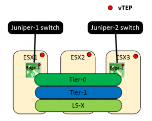
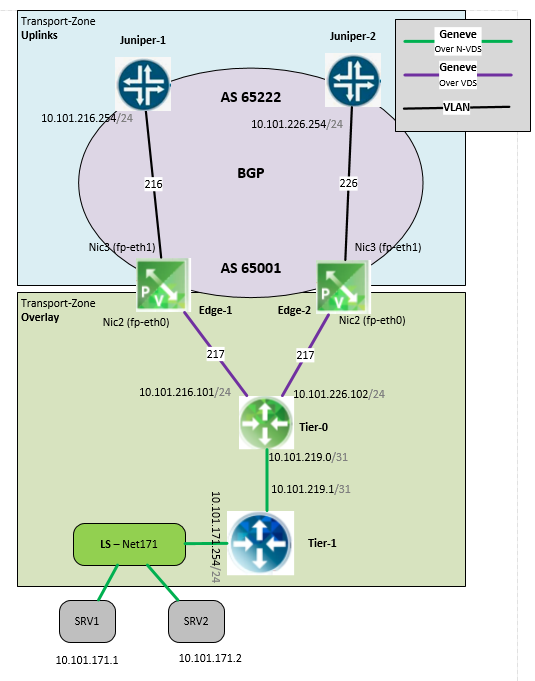
This is my NSX-T lab physical topology

It’s took me some time to find where to configure the Edge uplink IP address 🙂 you do it at Tier-0,
Tier-0 communicate with the edge via Geneve

NSX-T (ver 2.4) support only static routes and BGP for north-south,
i used BGP (because i have 2 active edges),


logical topology

Some more differences

NSX-VNSX-T
ManagenetvCenterNSX Manager
OverlayVXLANGeneve
East west routerDLR
(distributed)
Tier 1
(distributed)
North south router Edge
(not distributed)
Tier 0 (distributed)
but traffic flow via the edge
(not distributed)
Virtual switchLogical switch Logical switch

Controllers

controllers

NSX Manager
(starting with ver 2.4)
PlatformvSpherevSphere, OpenStack,
Containers (PKS)

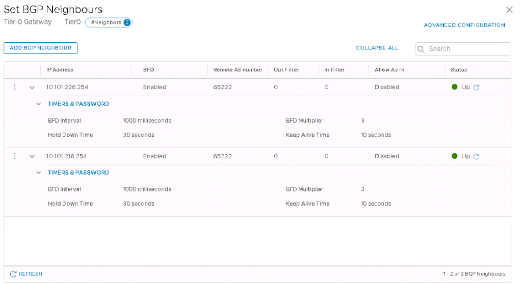
NSX-T BGP configuration

I used BFD, because without BFD in case of an age failure i had more the 1 minute packet loss, with BFD it’s around 2 seconds packet loss
I configured Interval 1000 (1 second) and multiplier 3

BGP config:

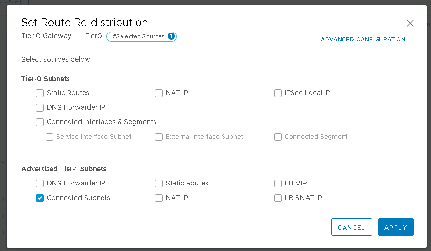
Route redistribution

Configure Tier-1 route redistribution into BGP
(this is done via Tier-0)

Juniper-1 BGP configuration

set interfaces xe-0/2/2 unit 0 family ethernet-switching vlan members v216
set interfaces irb unit 216 family inet address 10.101.216.254/24
set vlans v216 vlan-id 216
set vlans v216 l3-interface irb.216
set protocols bgp local-as 65222
set protocols bgp group SDDC-NSX-T_edge1 type external
set protocols bgp group SDDC-NSX-T_edge1 hold-time 30
set protocols bgp group SDDC-NSX-T_edge1 peer-as 65002
set protocols bgp group SDDC-NSX-T_edge1 neighbor 10.101.216.101 export export-route
set protocols bgp group SDDC-NSX-T_edge1 neighbor 10.101.216.101 bfd-liveness-detection version 1
set protocols bgp group SDDC-NSX-T_edge1 neighbor 10.101.216.101 bfd-liveness-detection minimum-interval 1000
set protocols bgp group SDDC-NSX-T_edge1 neighbor 10.101.216.101 bfd-liveness-detection multiplier 3
set protocols bgp group SDDC-NSX-T_edge1 neighbor 10.101.216.101 bfd-liveness-detection holddown-interval 0
set policy-options policy-statement export-route term local-routes from route-filter 0.0.0.0/0 exact
set policy-options policy-statement export-route term local-routes then accept

Juniper-2 BGP configuration

set interfaces xe-0/2/2 unit 0 family ethernet-switching vlan members v226
set interfaces irb unit 226 family inet address 10.101.226.254/24
set vlans v226 vlan-id 226
set vlans v226 l3-interface irb.226
set protocols bgp local-as 65222
set protocols bgp group SDDC-NSX-T_edge2 type external
set protocols bgp group SDDC-NSX-T_edge2 hold-time 30
set protocols bgp group SDDC-NSX-T_edge2 peer-as 65002
set protocols bgp group SDDC-NSX-T_edge2 neighbor 10.101.226.102 export export-route
set protocols bgp group SDDC-NSX-T_edge2 neighbor 10.101.226.102 bfd-liveness-detection version 1
set protocols bgp group SDDC-NSX-T_edge2 neighbor 10.101.226.102 bfd-liveness-detection minimum-interval 1000
set protocols bgp group SDDC-NSX-T_edge2 neighbor 10.101.226.102 bfd-liveness-detection multiplier 3
set protocols bgp group SDDC-NSX-T_edge2 neighbor 10.101.226.102 bfd-liveness-detection holddown-interval 0
set policy-options policy-statement export-route term local-routes from route-filter 0.0.0.0/0 exact
set policy-options policy-statement export-route term local-routes then accept

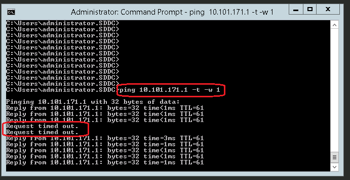
Ping test
I disconnected the link between Juniper-1 and Edge-1, only 2 seconds packet loss, BFD is working 🙂

NSX-T Troubleshooting


Whith NSX-T Tier-0 and Tier-1 troubleshooting is done via the Edge,
First you need to connect to the relevant Tier (via the ‘vrf’ command)

Juniper Troubleshooting


show bgp summary
show bfd session

Summary

With NSX-T use BGP & BFD in case you have more the 1 active NSX edge

The post <img src="http://www.sharontools.com/wp-content/uploads/2013/09/me-bw-150x150.jpg" width="30" height="30" alt="sharon saadon" class="avatar avatar-30 wp-user-avatar wp-user-avatar-30 alignnone photo" />VMware NSX-T and Juniper dynamic routing via BGP appeared first on SharonTools.
Cisco ACI and NSX-T integration

$
0
0

I was always sure that ACI and NSX-T can work together, today i tested it , i connected My NSX-T lab to my ACI lab via BGP

This is the topology:

Cisco ACI configuration:

ACI version 4.0(3d)

  1. At our SDDC tenant i created a new VRF named NSX-T (Because i already had a L3OUT at SDDC VRF)
  2. At Access-> Fabric policies I configured a new external routed domain with interfaces 1/7 at leafs 101,102 and allow VLANs 131 & 132 (a new VLAN pool)
  3. I created a new L3OUT named NSX-T with this configuration:
  • VRF: NSX-T
  • External routed domain: NSX-T-Ext-domain
  • Enable BGP
  • Enable Default Leak Policy (advertise default route to NSX-T)
  • Node profile: Node101
  • BGP peer connectivity: Address:10.101.231.101
  • Enable Peer control: Bidirectional forwarding detection (BFD)
  • Remote AS 65102
  • Local AS 65101 (Must not match MP-BGP EVPN AS, if it’s match BGP neighbor status will be IDLE)
  • BGP timers: 180 , 60 (if you do not enable BFD , configure Keepalive – 1, hold – 3)
  • Create BFD Interface profile with timers: 999, 999, 999, multiplier 3 (This is the MAX for ACI, the min for NSX-T is 1000 :), but it’s working)
  • Networks – subnets (also called external EPG) – 0.0.0.0/0
  • Enable only ‘External Subnets for the External EPG’
  • And the same for Node102

NSX-T configuration

NSX-T version 2.4

  1. Configure new regular vSwitch at each ESX at the cluster that have NSX-T Edge with the relevant physical port and relevant VLAN for the edge Uplink
  2. Configured 2 uplinks at Tier-0 via Edge-1 and Edge-2
  3. BGP timers: 180 , 60 (if you do not enable BFD , configure Keepalive – 1, hold – 3)
  4. BFD timers : Interval – 1000, multiplier – 3 (1000 is the minimum for Physical uplinks)
  5. At Tier-0 Configure route redistribute of Tier-1 Connected Subnets

BGP neighborship

And… It’s working

NSX-T

ACI

Troubleshooting

ACI

SSH to the relevant leaf and Check BGP neigbhors

Leaf-102# show ip bgp summary vrf SDDC:NSX-T
BGP summary information for VRF SDDC:NSX-T, address family IPv4 Unicast
BGP router identifier 10.101.255.102, local AS number 65001
BGP table version is 12, IPv4 Unicast config peers 1, capable peers 1
5 network entries and 5 paths using 800 bytes of memory
BGP attribute entries [5/720], BGP AS path entries [1/10]
BGP community entries [0/0], BGP clusterlist entries [1/4]
Neighbor V AS MsgRcvd MsgSent TblVer InQ OutQ Up/Down State/PfxRcd
10.101.232.102 4 65102 7248 7193 12 0 0 00:07:33 1

SSH to the relevant leaf and check route table:

Leaf-102# show ip route vrf SDDC:NSX-T
IP Route Table for VRF “SDDC:NSX-T”
‘ denotes best ucast next-hop ‘*’ denotes best mcast next-hop
‘[x/y]’ denotes [preference/metric]
‘%’ in via output denotes VRF
10.101.171.0/24, ubest/mbest: 1/0
*via 10.101.232.102%SDDC:NSX-T, [20/0], 07:10:57, bgp-65001,
external, tag 65101
10.101.231.0/24, ubest/mbest: 1/0
*via 10.1.112.64%overlay-1, [200/0], 00:37:56, bgp-65001, internal, tag 65001
10.101.232.0/24, ubest/mbest: 1/0, attached, direct
*via 10.101.232.254, vlan74, [1/0], 1d03h, direct
10.101.232.254/32, ubest/mbest: 1/0, attached
*via 10.101.232.254, vlan74, [1/0], 1d03h, local, local
10.101.249.0/24, ubest/mbest: 1/0, attached, direct, pervasive
*via 10.1.224.66%overlay-1, [1/0], 1d02h, static, tag 4294967294
10.101.255.101/32, ubest/mbest: 1/0
*via 10.1.112.64%overlay-1, [1/0], 00:37:56, bgp-65001, internal, tag 65001
10.101.255.102/32, ubest/mbest: 2/0, attached, direct
*via 10.101.255.102, lo3, [1/0], 1d03h, local, local
*via 10.101.255.102, lo3, [1/0], 1d03h, direct

SSH to the relevant leaf and check BFD status:

Leaf-102# show bfd neighbors vrf SDDC:NSX-T
OurAddr NeighAddr LD/RD RH/RS Holdown(mult) State Int Vrf
10.101.232.254 10.101.232.102 1090519042/385914307 Up 3000(3) Up Vlan74 SDDC:NSX-T

NSX-T

SSH to the edge and check witch VRF uses Tier-0

edge2> get logical-router
Logical Router
UUID VRF LR-ID Name Type Ports
736a80e3-23f6-5a2d-81d6-bbefb2786666 0 0 TUNNEL 3
c2a31082-fc16-4268-a510-2c35740a980c 3 3080 SR-Tier0 SERVICE_ROUTER_TIER0 6
26f6cc48-ad93-4b22-beee-7a1b8e030d8a 4 3075 SR-Tier1 SERVICE_ROUTER_TIER1 5

edge2> vrf 3
edge2(tier0_sr)>

Check BGP neighbors

edge2(tier0_sr)> get bgp neighbor summary
BFD States: NC – Not configured, AC – Activating,DC – Disconnected
AD – Admin down, DW – Down, IN – Init,UP – Up
BGP summary information for VRF default for address-family: ipv4Unicast
Router ID: 10.101.232.102 Local AS: 65102
Neighbor AS State Up/DownTime BFD InMsgs OutMsgs InPfx OutPfx
169.254.0.130 65102 Estab 04:24:00 NC 40706 40715 4 4
10.101.232.254 65101 Estab 00:16:00 UP 11551 11642 1 2
10.101.231.254 65101 Activ never NC 0 0 0 0

Check BFD sessions

edge2(tier0_sr)> get bfd-sessions
BFD Session
Dest_port : 3784
Diag : No Diagnostic
Encap : vlan
Forwarding : last true (current true)
Interface : 54e35cab-c821-4f9d-aed1-f93e042ad08c
Keep-down : false
Last_cp_diag : No Diagnostic
Last_cp_rmt_diag : No Diagnostic
Last_cp_rmt_state : up
Last_cp_state : up
Last_fwd_state : UP
Last_local_down_diag : No Diagnostic
Last_remote_down_diag : No Diagnostic
Last_up_time : 2019-04-01 18:58:57
Local_address : 10.101.232.102
Local_discr : 385914307
Min_rx_ttl : 255
Multiplier : 3
Received_remote_diag : No Diagnostic
Received_remote_state : up
Remote_address : 10.101.232.254
Remote_admin_down : false
Remote_diag : No Diagnostic
Remote_discr : 1090519041
Remote_min_rx_interval : 999
Remote_min_tx_interval : 999
Remote_multiplier : 3
Remote_state : up
Router : c2a31082-fc16-4268-a510-2c35740a980c
Router_down : false
Rx_cfg_min : 1000
Rx_interval : 1000
Service-link : false
Session_type : LR_PORT
State : up
Tx_cfg_min : 1000
Tx_interval : 1000

Check routing table

edge2(tier0_sr)> get route bgp
Flags: t0c – Tier0-Connected, t0s – Tier0-Static, B – BGP,
t0n – Tier0-NAT, t1s – Tier1-Static, t1c – Tier1-Connected,
t1n: Tier1-NAT, t1l: Tier1-LB VIP, t1ls: Tier1-LB SNAT,
t1d: Tier1-DNS FORWARDER, > – selected route, * – FIB route
Total number of routes: 3
b > * 0.0.0.0/0 [20/0] via 10.101.232.254, uplink-277, 00:00:46
b 169.254.0.128/25 [200/0] via 169.254.0.130, inactive, 00:29:31
b > * 10.101.231.0/24 [200/0] via 169.254.0.130, inter-sr-279, 00:29:31

NSX-T edge – packet capture – to use with wireshark

set capture session 1 interface fp-eth0 direction dual
set capture session 1 file capture1.pcap

the file is saved at – /var/vmware/nsx/file-store/ , in order to copy this file via WinSCP, you need first to enable service SSH at CLI and then login via console as root and enable remote root login at sshd_config file

Summery

ACI to NSX-T BGP is working 🙂
for this physical interface (1/7) i did not used VMM domain at ACI
Last thought – what is the East-West packet size ? (it’s Geneve over VXLAN)

The post <img src="http://www.sharontools.com/wp-content/uploads/2013/09/me-bw-150x150.jpg" width="30" height="30" alt="sharon saadon" class="avatar avatar-30 wp-user-avatar wp-user-avatar-30 alignnone photo" />Cisco ACI and NSX-T integration appeared first on SharonTools.

Viewing all 15 articles
Browse latest View live